Honda CT90 Wire Harness Detailed Information
I recently had a number of CT90 main wire harnesses that I had to do some minor repairs on, so I thought I would do a post to share some detailed information that might be beneficial to someone else working on their CT90's wire harness or maybe even someone wanting to build one from scratch.
At the beginning of this post I'll explain some of the differences between the wire harnesses and then later in the post I will show the 1971 version of a CT90 harness completely disassembled so you can see what the individual wires look like and I will detail the process I follow to reassemble that harness back into an installable configuration.
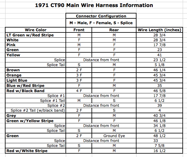
I also included detailed information on the measurements related to the harness and a table of how long each of the individual wires are in case someone decided they wanted to build a harness from scratch.
Wire harness Differences
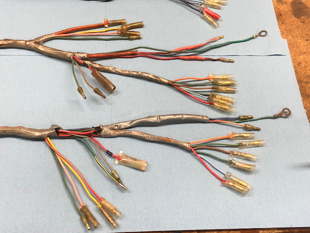
Here is a picture of the three harnesses I was working on.
The harness at the bottom in the picture above was from a 1971 CT90, the one in the middle was off a 1972 or 73 CT90, and the one at the top of the picture was off of a 1975 CT90. The harnesses are shown with the end on the left being the end that connects in the headlight bucket at the front of the bike.
While the bottom two harnesses are functionally identical, there are a few differences worth pointing out.
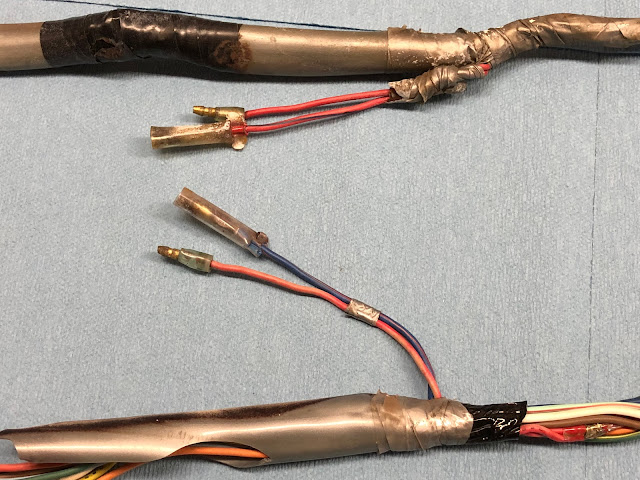
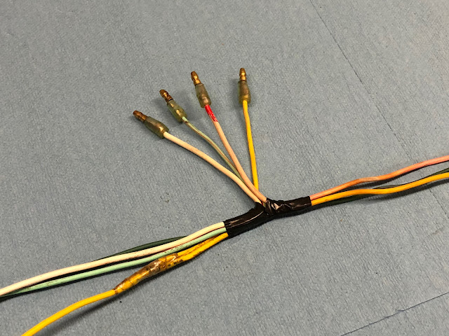
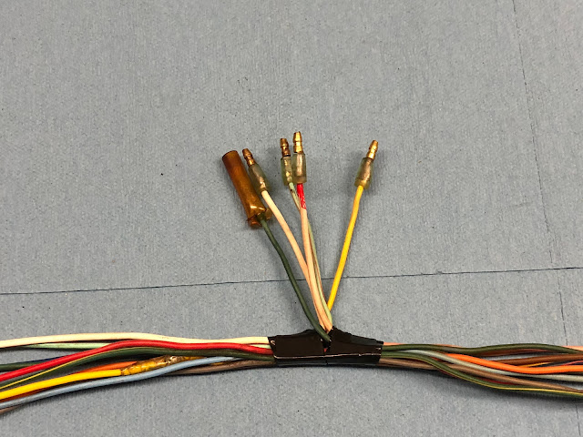
The first difference is at the left end of the harness that terminates in the headlight bucket. The primary difference is that the one wire that has a receptacle that accepts four male plugs is red with a small black band on the harness from the 1971 CT90 as shown in the picture below, but on the harness from the 1972 or 73 CT90 that same wire is black with a small red band and is the second picture below. The function of the wire is identical between the two harnesses, but Honda for some reason choose to make a change to the color of the wire.
Another minor difference between these two harnesses is with the color of one of the wires leading to the ignition switch.
The key difference is that the wire coming to the switch from the battery is blue with a red stripe on the 1971 harness and on the 1972 or 73 harness the wire is red with a blue stripe. Its not a major difference, but if you were looking for a used CT90 wire harness and you saw the difference you shouldn't let it keep you from buying the harness.
Another difference between these two wire harnesses is with details on the wire from the battery to the rectifier.
On the wire from the battery to the rectifier (red with a white stripe) Honda ended up adding some woven sheathing to the end going to the rectifier on the 1972 or 73 version of the harness compared to the earlier version that didn't have any sheathing which may be an indication that there were issues with this wire chaffing and shorting out. The cheating is shown in the picture below.
With the wire harness off of the 1975 CT90 there are the obvious differences with the addition of plastic connectors used to connect to the generator and rectifier, but at the end that terminates in the headlight bucket there is a significant change in that there are now twelve wires instead of the ten used on the older configurations of the CT90 wire harnesses.
In addition to the two additional wires on the 1975 CT90 wire harness, there are three short jumper bundles as shown in the picture below that are required to get the harness hooked up correctly to the other connections in the headlight bucket. So if you are starting a CT90 project and you are missing the main wire harness you also need to find the three unique short jumper wires to complete your project.
1971 CT90 Wire Harness Detailed Information
Since I had work to do on my 1971 CT90 wire harness I thought I would provide some detailed information related to the dimensions of the bundle itself and then also the individual wires that make up the harness.
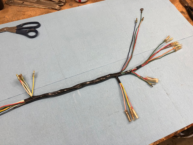
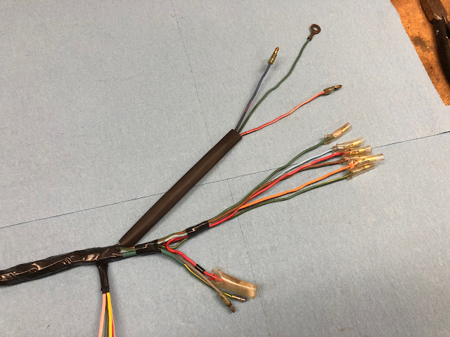
The following are pictures of the harness I will be providing detailed information on and then disassembling and then reassembling.
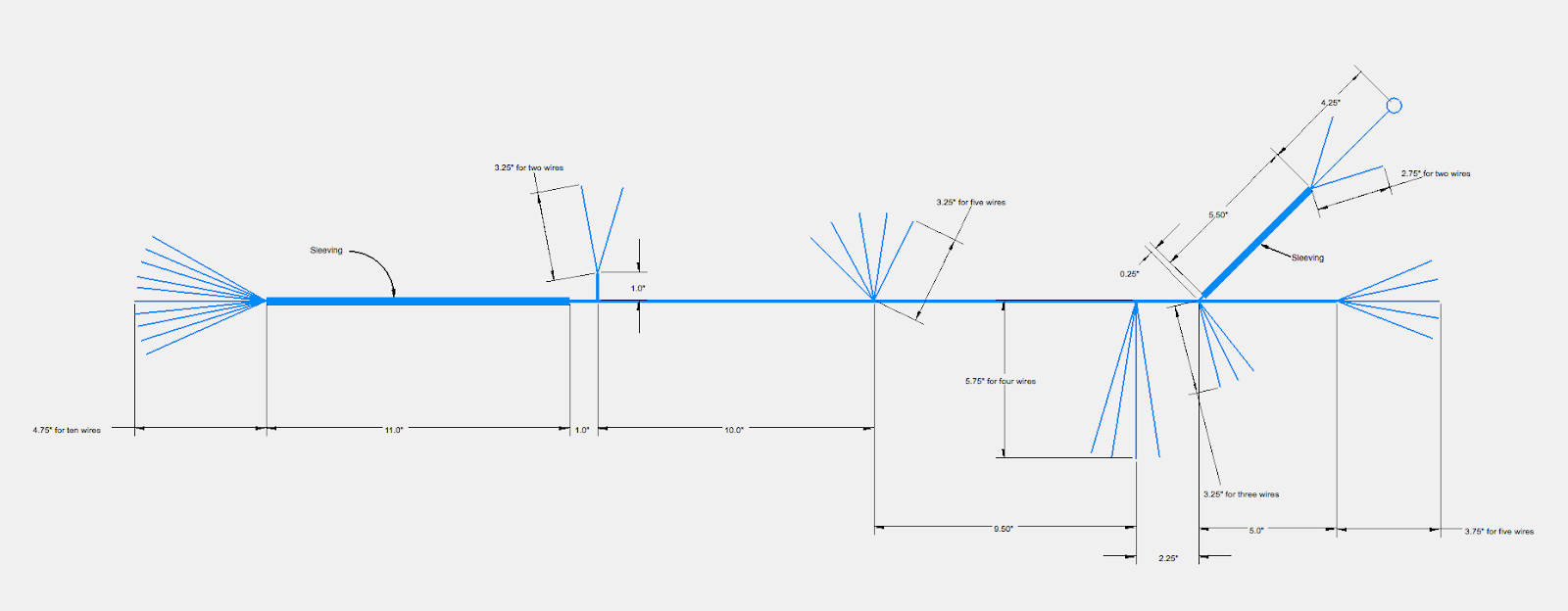
The drawing below has the basic dimensional information for the 1971 CT90 wire harness. Most of the dimensions shown can vary by a 1/4 inch from harness to harness, but are the average values I obtained measuring the couple of harnesses I have currently.
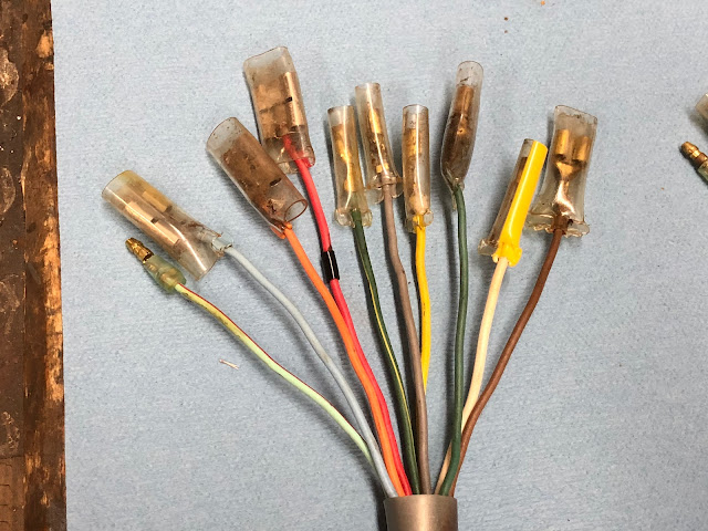
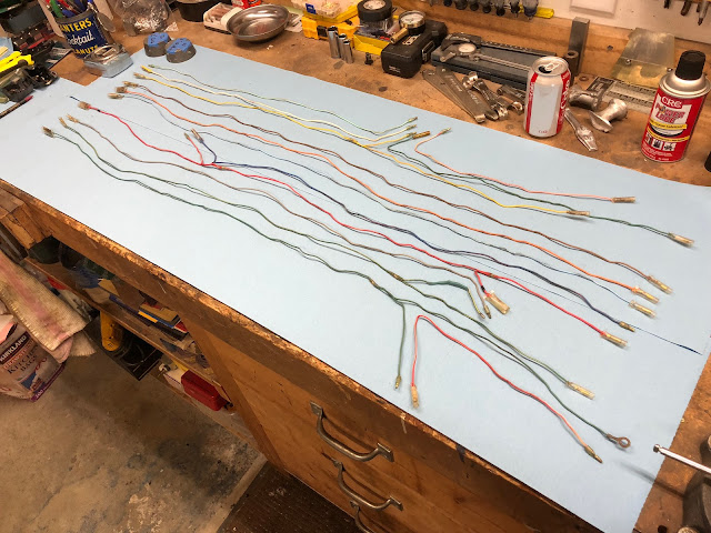
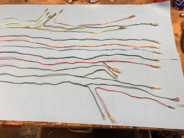
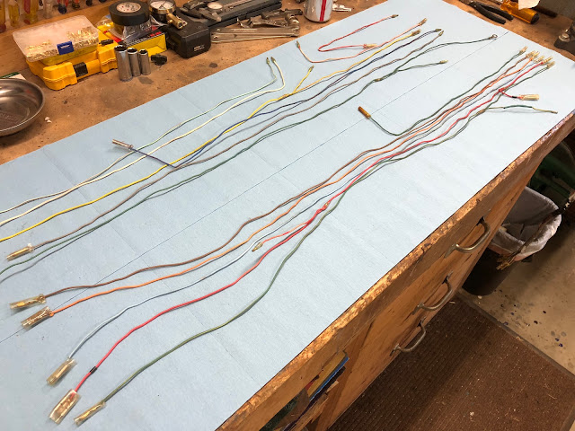
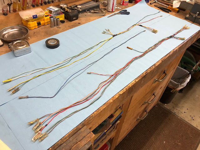
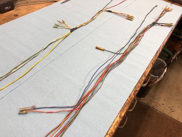
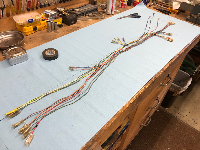
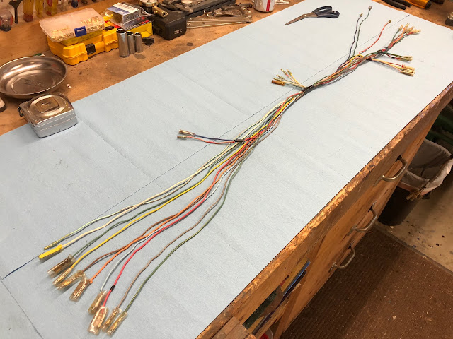
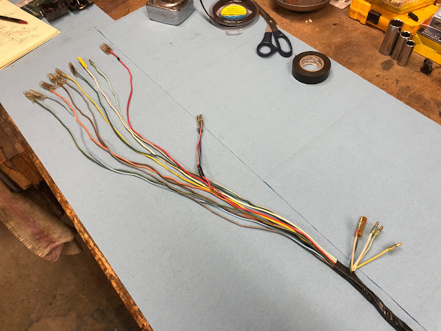
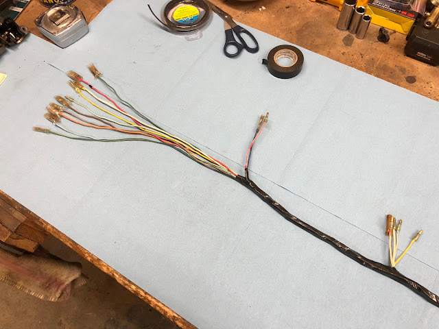
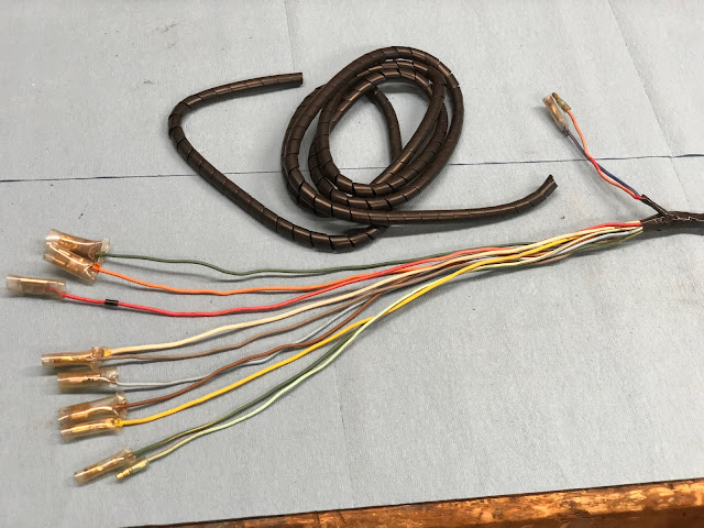
When you take all the tape and sleeving off the wire harness and separate the wires this is what you end up with.
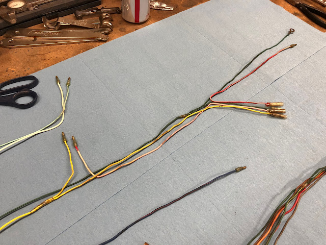
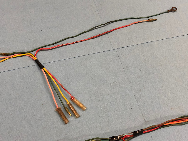
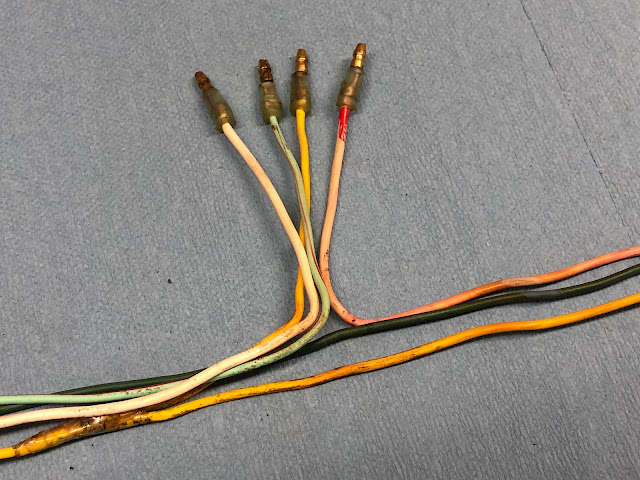
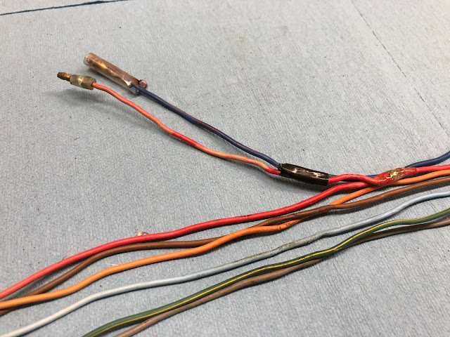
Going from left to right on the harness, here are a few detailed photos so that you can see the individual splices that are internal to the bundle.
The table below has detailed information on the length of each wire and how it is terminated at each end. The reference to "Distance from front" means the distance measured from the end of the wire harness that terminates in the headlight bucket.
Reassembling the CT90 Wire Harness
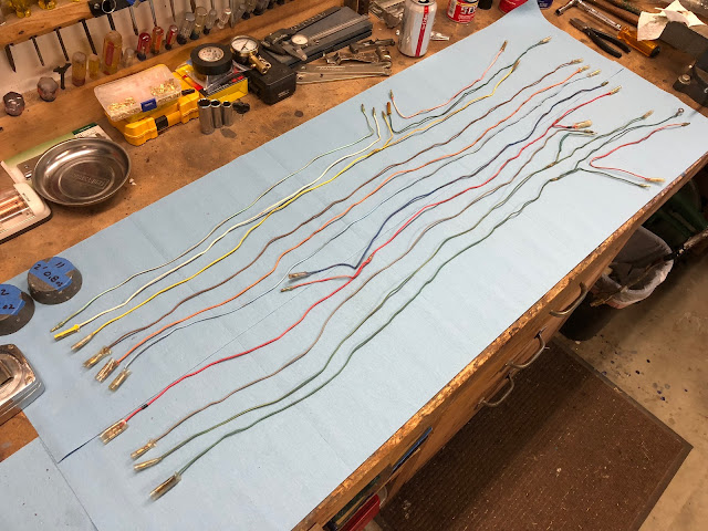
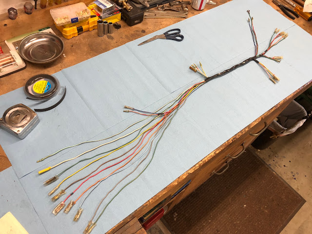
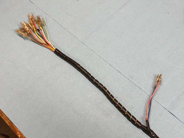
The following series of photos show how I go about taking all the individual wires back into a complete harness. I basically start to group specific wires together and then tape key points and then finally start taping and add sleeving working from the center outward.
While not stock, I used spiral sleeving wrap covered with a layer of tape to protect the section of harness up near the front forks that sees regular movement and possible chaffing.
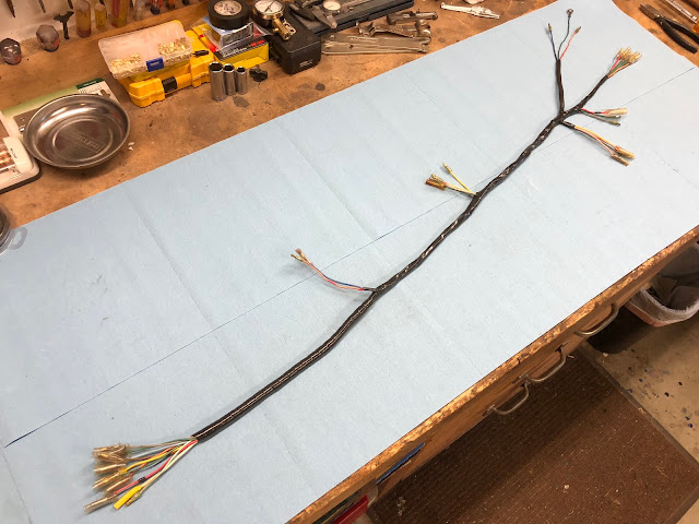
The end product is a completed functional harness. The materials are available from DrATV to reassemble your harness so it is just like a stock CT90 harness, but for all the bikes I build my focus is to just have a reliable runner. In the future I do plan on taking two of my CT90's and do a complete restoration and will rebuild the harnesses from those bikes to be as stock as possible.
I hope this information is helpful and good luck with your future Honda CT90 wiring harness efforts.
Links to Related Posts
CT90 Rectifier Upgrade
How to Test of a CT90 Condenser
Basic CT90 Ignition Coil Check
Helpful Links (Shop Manuals, Wire Diagram, Model Information, etc.)
Link to page with listing of CT90 parts available on Amazon
At the beginning of this post I'll explain some of the differences between the wire harnesses and then later in the post I will show the 1971 version of a CT90 harness completely disassembled so you can see what the individual wires look like and I will detail the process I follow to reassemble that harness back into an installable configuration.
I also included detailed information on the measurements related to the harness and a table of how long each of the individual wires are in case someone decided they wanted to build a harness from scratch.
Wire harness Differences
Here is a picture of the three harnesses I was working on.
While the bottom two harnesses are functionally identical, there are a few differences worth pointing out.
The first difference is at the left end of the harness that terminates in the headlight bucket. The primary difference is that the one wire that has a receptacle that accepts four male plugs is red with a small black band on the harness from the 1971 CT90 as shown in the picture below, but on the harness from the 1972 or 73 CT90 that same wire is black with a small red band and is the second picture below. The function of the wire is identical between the two harnesses, but Honda for some reason choose to make a change to the color of the wire.
Another minor difference between these two harnesses is with the color of one of the wires leading to the ignition switch.
The key difference is that the wire coming to the switch from the battery is blue with a red stripe on the 1971 harness and on the 1972 or 73 harness the wire is red with a blue stripe. Its not a major difference, but if you were looking for a used CT90 wire harness and you saw the difference you shouldn't let it keep you from buying the harness.
Another difference between these two wire harnesses is with details on the wire from the battery to the rectifier.
On the wire from the battery to the rectifier (red with a white stripe) Honda ended up adding some woven sheathing to the end going to the rectifier on the 1972 or 73 version of the harness compared to the earlier version that didn't have any sheathing which may be an indication that there were issues with this wire chaffing and shorting out. The cheating is shown in the picture below.
With the wire harness off of the 1975 CT90 there are the obvious differences with the addition of plastic connectors used to connect to the generator and rectifier, but at the end that terminates in the headlight bucket there is a significant change in that there are now twelve wires instead of the ten used on the older configurations of the CT90 wire harnesses.
In addition to the two additional wires on the 1975 CT90 wire harness, there are three short jumper bundles as shown in the picture below that are required to get the harness hooked up correctly to the other connections in the headlight bucket. So if you are starting a CT90 project and you are missing the main wire harness you also need to find the three unique short jumper wires to complete your project.
1971 CT90 Wire Harness Detailed Information
Since I had work to do on my 1971 CT90 wire harness I thought I would provide some detailed information related to the dimensions of the bundle itself and then also the individual wires that make up the harness.
The following are pictures of the harness I will be providing detailed information on and then disassembling and then reassembling.
The drawing below has the basic dimensional information for the 1971 CT90 wire harness. Most of the dimensions shown can vary by a 1/4 inch from harness to harness, but are the average values I obtained measuring the couple of harnesses I have currently.
When you take all the tape and sleeving off the wire harness and separate the wires this is what you end up with.
Going from left to right on the harness, here are a few detailed photos so that you can see the individual splices that are internal to the bundle.
The table below has detailed information on the length of each wire and how it is terminated at each end. The reference to "Distance from front" means the distance measured from the end of the wire harness that terminates in the headlight bucket.
Reassembling the CT90 Wire Harness
The following series of photos show how I go about taking all the individual wires back into a complete harness. I basically start to group specific wires together and then tape key points and then finally start taping and add sleeving working from the center outward.
While not stock, I used spiral sleeving wrap covered with a layer of tape to protect the section of harness up near the front forks that sees regular movement and possible chaffing.
The end product is a completed functional harness. The materials are available from DrATV to reassemble your harness so it is just like a stock CT90 harness, but for all the bikes I build my focus is to just have a reliable runner. In the future I do plan on taking two of my CT90's and do a complete restoration and will rebuild the harnesses from those bikes to be as stock as possible.
I hope this information is helpful and good luck with your future Honda CT90 wiring harness efforts.
Links to Related Posts
CT90 Rectifier Upgrade
How to Test of a CT90 Condenser
Basic CT90 Ignition Coil Check
Helpful Links (Shop Manuals, Wire Diagram, Model Information, etc.)
Link to page with listing of CT90 parts available on Amazon

















These step by step instructions are the best!
ReplyDeleteIs there any chance you could help me understand how the blue small pigtail hooks up for the 1975 harness? I cannot figure it out and it is not clear in the 1975-76 diagram. I would be very appreciative!
ReplyDeleteThanks for creating such a useful resource and sharing it with all to benefit from its a rare opportunity
ReplyDeleteThanks for creating such a useful resource and sharing it for all to benefit from
ReplyDeleteThanks for creating such a useful resource and sharing it for all to benefit from
ReplyDeleteI'm new to the workings of the CT90 and this is the best description of the wiring harness that I've found.
ReplyDeleteI have been inspecting my harness and have found some breaks and continuity problems so I need to replace some wires but I'm not sure what type or size of wire to use. Someone said that it might be 1.5mm but wasn't sure. Do you know if it's all the same and if so what it is.
Thanks
Phil
L
ReplyDeleteBig thank you for sharing this! It's highly commendable detail and methodical job you did, Michael!
ReplyDelete